blainehansen
Arcade Music Generator
A Digital Systems Design class project I did in 2012.
published: November 4, 2015 - last updated: May 13, 2024
This is the only school project I'll put in my portfolio, because it's the only one with any opportunity to exercise design creativity. In 2012 as a group project for a Digital Systems Design class, we built a music sequencer based on this earslap project (opens new window). To build a web app version of this would have been really simple, but ours had to essentially be an arcade game, with both hardware and software components all implemented by us.
Here's a video demonstrating the finished product. Be warned, we had just pulled a nasty all-nighter to comb out the last of the problems, and it hadn't treated any of us very well. After I'm done with my portion of the presentation I get kind of a look on my face in the background haha. I'm the first person, the one who shows how the interface works.
We used verilog and an FPGA to implement a processor and IO devices to interface with our keyboard and speakers. That processor then ran an assembly language program in a version of cr16 designed for that class. We also had to implement an assembler to compile our program into machine code, and we used Ruby to do that. Although we all contributed to all areas of the entire project, I was in charge of the assembly program, and I wrote 2,200 lines of cr16 assembly code to make it work. I suggested that we imitate that earslap project, and I figured out the algorithm.
The application has two main phases, an Input phase and a Run phase.
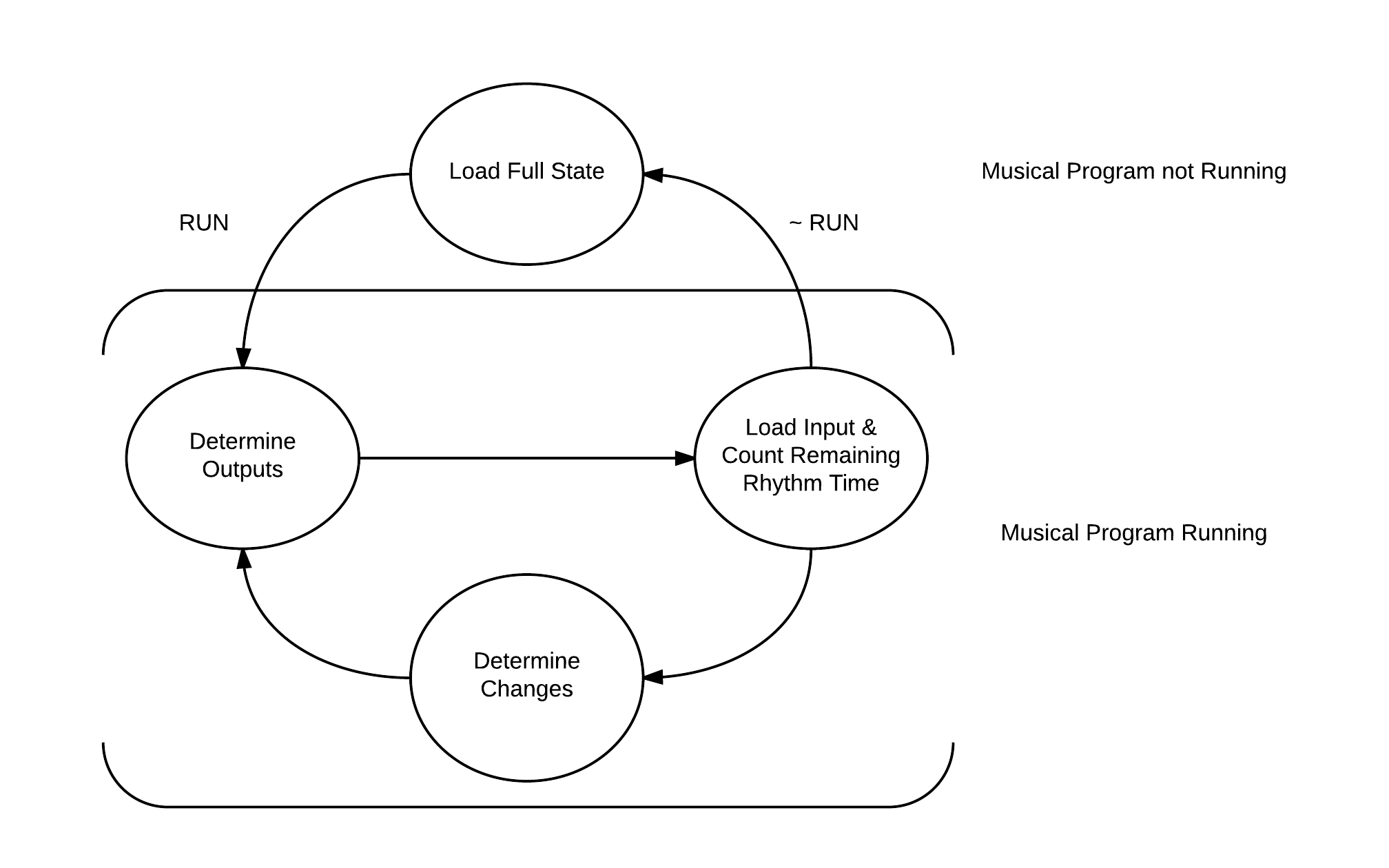
And here's our pseudo-code outline of the program:
.input_phase
	while (!run_program) {
		receive_input()
		check_input_and_make_changes()
	}
	goto run_phase

.run_phase
	while (true) {
		determine_current_outputs()

		while (time_remaining_for_tempo) {

			receive_tempo_and_key_input()
			check_input_and_make_changes()

		}

		if (!run_program) {
			goto input_phase
		}

		for (square in state_squares) {
			update_scratch(square)
		}

		load_scratch_to_state_squares()
	}
In the Input phase, users can enter keystrokes in order to place directional arrow blocks on the eight-by-eight square grid. The directional keys are used to navigate a highlighted active square across the grid, with the ability to wrap from one edge of the grid to another upon moving past it, and enter is used to change the state of the currently highlighted grid square. The ordering of the state changes is: Empty, Up, Right, Down, Left, Empty. The return to empty was added to enable users to remove arrow blocks if they reconsidered them.
In order to represent the generator's internal data, a 64 word section of memory was allocated as the "State Buffer". This array represented the 64 grid squares, starting from the top left corner, addressed as offset 0, moving left to right across columns, and then down rows, making the final address offset of 63 the bottom right corner. Each grid square could have a value from 0 to 15, representing the state of that square. The state meanings were as follows:
Unoccupied = 0; Up = 1; Down = 2; Left = 3; Right = 4;
# and then abbreviated for direction:
RL = 5; RU = 6; RD = 7; LU = 8; LD = 9; UD = 10;
RLU = 11; RLD = 12; RUD = 13; LUD = 14;
RULD = 15;
We had trouble figuring out how to make the Input phase navigation happen. The scheme used in the final application was to not store any information about the currently highlighted square in the state buffer at all, since for every existing normal state there would need to be another "highlighted" version of this state. The highlighted square number was instead kept in a register during the input phase, and used a function to update the frame buffer with the single highlighted square every time user input is given indicating a change. This must be done after any function call to write the frame buffer, since a call to write frame buffer will erase any highlighted squares as this information is not kept in the state buffer. This strategy still required extra glyphs for each visual square, but the internal data was left unchanged, which was a much needed simplification. A function was also used to signal that enter was pressed on a certain square. This function handled reading that square's data, and deciding how to update it properly. The sequence of updating the frame buffer and then highlighting the current square is also performed after this enter function is completed.
From this Input phase the Run phase is initiated by pressing the "Space" key, at which point arrow block input and modifications are no longer accepted, and the program runs autonomously according to the generator rules. At any time the user can stop the Run phase and move back into the Input phase by again pressing "Space". The rules are simple. Every application cycle, which is timed by an IO controlled hardware clock detailed in the IO portion of this report, each arrow block moves one grid square in the direction corresponding to it's internal state, either Up, Down, Left, or Right. Upon colliding with any of the four grid edges, a tone from a musical scale is played, corresponding to the row or column number (whichever is applicable) of the collision location. The arrow block then turns in the opposite direction to face directly away from the wall. These two changes, the tone and the turn, happen on the same application cycle. When arrow blocks land on the same grid square, they collide, and each arrow block turns clockwise. Up to four arrow blocks may possibly collide in one square at a time, since there are no diagonal movements, and the only four-way collision possible therefore includes all four directions simultaneously.
The first stage of the Run phase determines the next state, or the grid arrangement to change to on the next application cycle. At first, it was unclear how to update the state buffer without writing over important values, but this problem was solved with a second buffer identical in size and arrangement as the state buffer, called the "Scratch Buffer". As the program iterates through each grid square in the state buffer, the scratch buffer holds the intermediate values as they are calculated, and is then written back into the state buffer after this stage is complete. This prevents new state and old state from becoming entangled. The change determination algorithm first loads the current state from the square being handled, then checks to see if there are any wall collisions. If there are, the offending arrows are "peeled" from the state number (if an RL is against the right edge, the R is removed and the state is updated to simply L, etc.) and the corresponding tone is queued. The flipped version of the colliding arrow is then written to the scratch buffer in it's proper location, and the program continues to check the remaining state. The program checks the state for each type of arrow in turn, peeling it from the state and passing it to a function that places it in the scratch buffer accordingly, until the state has been reduced to 0, and the program iterates to the next square. The step of updating the scratch buffer properly also has some complexity. A function is used that takes the arrow value to be written and the current square number. The state at the scratch buffer square must then be read, and it's value incorporated with the new arrow to become the new state value at that scratch buffer square.
The Run phase then enters a stage where it waits for the application timer to elapse while also checking user input. This stage is exited if the timer elapses or if the user presses "Space". In both exit cases, the frame buffer is updated with the fresh values of the state buffer calculated during the previous stage, the sound queue is pushed to the speakers and cleared, and execution jumps to either the Input phase or continues in the Run phase, depending on which exit was taken. If the Run phase continues, the application timer is reset using the IO interface defined, and the collision rotations are made. To make the collision rotations, the state buffer is iterated, and each square that has arrow collisions is rotated clockwise in place in the state buffer, since this doesn't move any arrows into other squares and thus doesn't require the scratch buffer. After this the determine next state stage is once again entered and the cycle continues infinitely if allowed. By placing the determination of next state as the first stage completed upon entering the Run phase, the application doesn't miss pushing any updates to the IO for the user to see.
The application was written in as modular a fashion as was possible, to make each step as easy to debug and coordinate as possible. Functions were written that performed checks on grid numbers to determine if they were on edges, a single function was used to overwrite the frame buffer with the state buffer, and another was used to write the state buffer with the contents of the scratch buffer after changes had been determined. The function handling the queuing of sound took a square location and queued the proper sound by performing an OR operation on the sound queue (held permanently during the entire application in r8) with a binary value containing a single one, corresponding to a sound. The maximum number of sounds that can be played on one application cycle is eight, as the rows and columns map to the exact same scale. This register is sent to the IO at the same time the frame buffer is updated with the current state, so that the sounds and the screen changes appear simultaneous, and the queue is then cleared for the next application cycle.
At its complete length, this application involves many comparisons, which were akin in structure to switch-case blocks. A likely improvement on this method would be to devise an appropriate assembly schema to ergonomically implement switch-case blocks. This would greatly reduce program complexity and size. Also, encoding the arrow states so that they could simply be added and subtracted to create collision states would have been very ergonomic. A proposed encoding that achieves unique collision states is Up = 1, Right = 3, Down = 7, Left = 15. This strategy also has the advantage that cycling to the next single arrow state merely requires a multiplication by two followed by an addition of one, with the exception of Left to Empty.
The application portion of this project on the whole went well. There were bugs in the code, mostly in the form of erroneous jumps or comparisons. A bug that caused a great deal of trouble, and the last one to be solved, was a mislabeled jump that caused an infinite loop if entered. This caused the program to crash whenever certain types of collisions happened. Successfully completing the project was very satisfying, and we all felt the experience was worthwhile. Despite the fact that it was incredibly hard and those 2,200 lines were really arduous, I loved seeing that come together and solving that problem.